1: Department of Biomedical Engineering, Duke University, Durham NC, USA.
2: Department of Computer Science, Duke University, Durham NC, USA.
3: Department of Electrical and Computer Engineering, Duke University, Durham NC, USA
4: Duke Forge, Duke University, Durham, NC 27708 USA
#These authors contributed equally to this work and are first authors.
Links to Paper Code and Dataset
It is challenging and time-consuming for trained technicians to visually examine blood smears to reach a diagnostic conclusion. A good example is the identification of infection with the malaria parasite, which can take upwards of ten minutes of concentrated searching per patient. While digital microscope image capture and analysis software can help automate this process, the limited field-of-view of high-resolution objective lenses still makes this a challenging task. Here, we present an imaging system that simultaneously captures multiple images across a large effective field-of-view, overlaps these images onto a common detector, and then automatically classifies the overlapped image’s contents to increase malaria parasite detection throughput. We show that malaria parasite classification accuracy decreases approximately linearly as a function of image overlap number. For our experimentally captured data, we observe a classification accuracy decrease from approximately 0.9-0.95 for a single non-overlapped image, to approximately 0.7 for a 7X overlapped image. We demonstrate that it is possible to overlap seven unique images onto a common sensor within a compact, inexpensive microscope hardware design, utilizing off-the-shelf micro-objective lenses, while still offering relatively accurate classification of the presence or absence of the parasite within the acquired dataset. With additional development, this approach may offer a 7X potential speed-up for automated disease diagnosis from microscope image data over large fields-of-view.
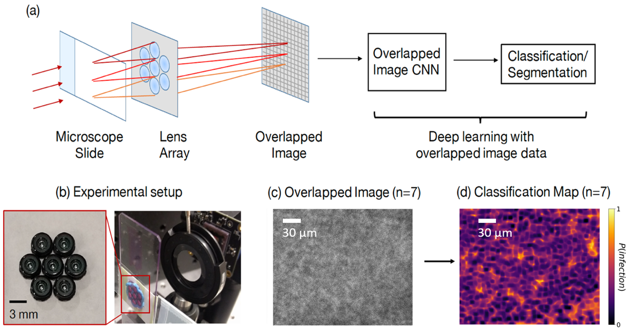
Figure 1. Summary of our overlapped imaging and classification approach. (a) An array of small lenses magnifies different regions of a sample of interest onto a single image sensor to form an overlapped image. A DNN, trained to classify overlapped image data, then classifies different sample regions into classes of interest. (b) Image of the experimental setup and lens array. (c) Example overlapped microscope image of a blood smear infected with the malaria parasite. (d) Associated classification map highlights the probability of infection within different image areas.
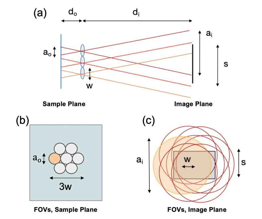
Figure 2. Overlapped imaging setup. (a) Imaging geometry with sample (on left) imaged by three lenses onto a single image sensor (on right) to form overlapped images across sensor area. (b) FOV of seven lenses at the sample plane, where FOVs of width a_o are separated by lens pitch w and do not overlap. (c) At the image plane, FOVs of width a_o overlap. Marked variables are listed in the Table 1.
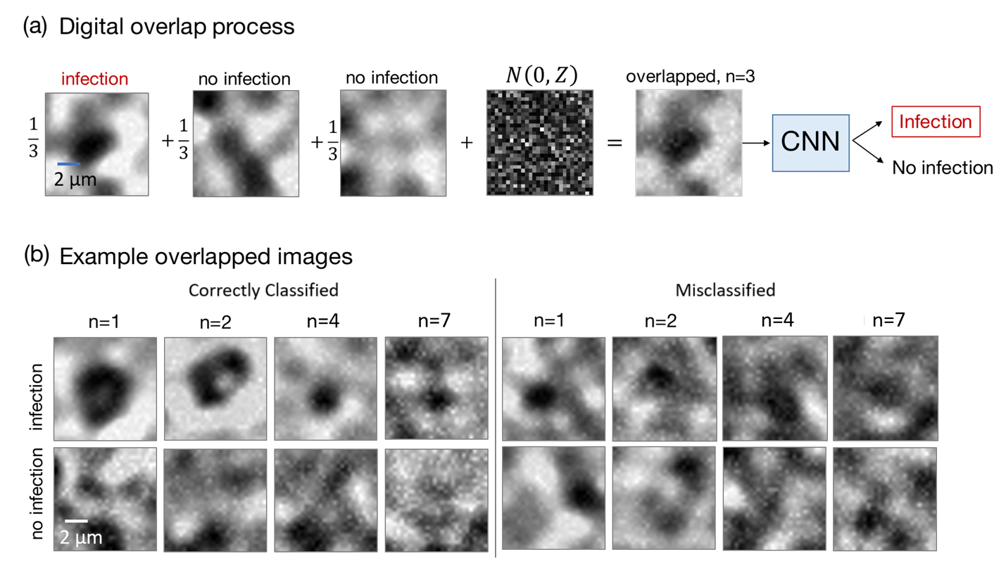
Figure 3. Digitally overlapped imaging experiment. (a) We generate digitally overlapped images by adding together patches of experimentally captured and annotated blood smear images from a standard microscope. Noise is also added to accurately model an overlapped microscope image. We train and validate our DNN with many digitally overlapped image examples, as shown in (b). At (top) are examples with one P. Falciparum parasite within the overlapped FOV, and at (bottom) are examples without any parasites, for different values of image overlap parameter n.
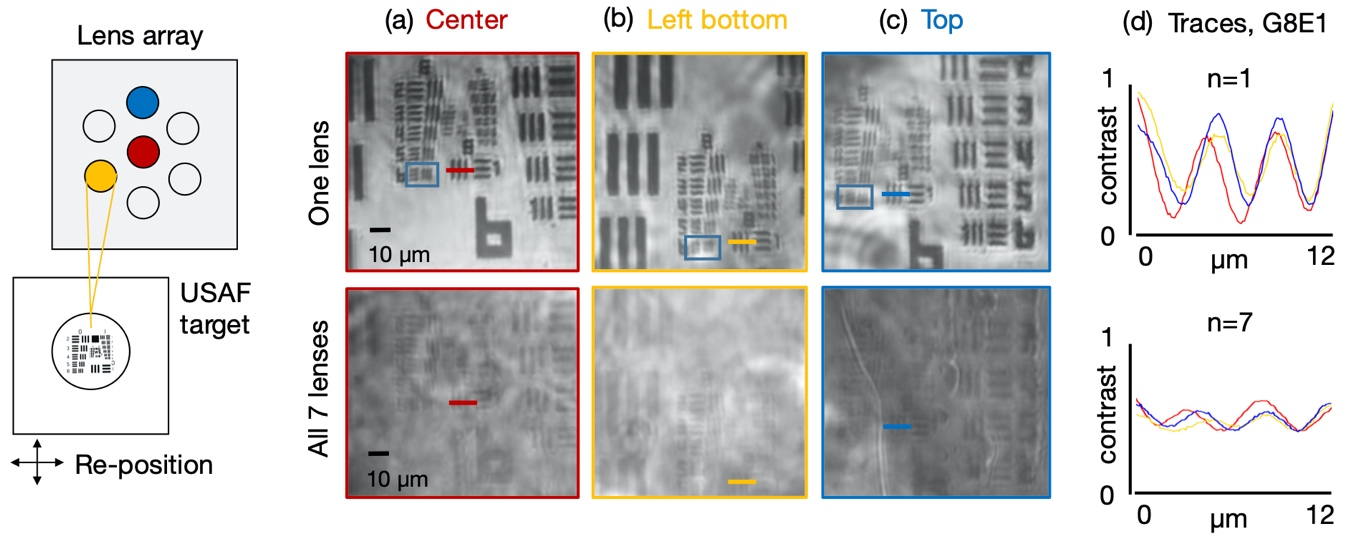
Figure 4. Overlapped images of a resolution target determine system resolution and contrast. Resolution target is positioned beneath one of n = 7 sub-lenses at a time, with all other sub-lenses blocked, for non-overlapped image capture. Example non-overlapped images (a) from the center sub-lens, (b) left-bottom sub-lens and (c) top sub-lens all exhibit approx.2 µ m full-pitch resolution limit (see blue boxes). N = 7 overlapped images (at bottom), captured by illuminating all sub-FOVs at each resolution target position, demonstrate the sample is still visible. (d) Traces through Group 8 Element 1 (colored lines, averaged over 20 rows) show approximately a 6X higher contrast for the non-overlapped images (top) versus the corresponding overlapped images (bottom).
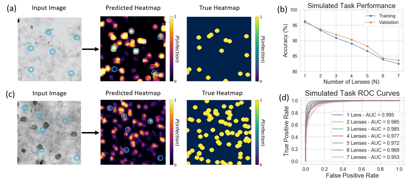
Figure 5: Results for Mobile Dataset, blue circles on images represent sample locations which are labelled to be infected with malaria (only a subset of the annotations is shown to avoid cluttering the image). Predicted heatmaps are generated with a trained DNN, while the true heatmap is generated from the annotations, both cover the same FOV. (a) Results for the single non-overlapped imaging case (i.e., standard imaging). (b) Task performance for all overlap conditions. (c) Results for the n = 7 overlapped imaging case. (d) ROC curves for all overlap conditions.
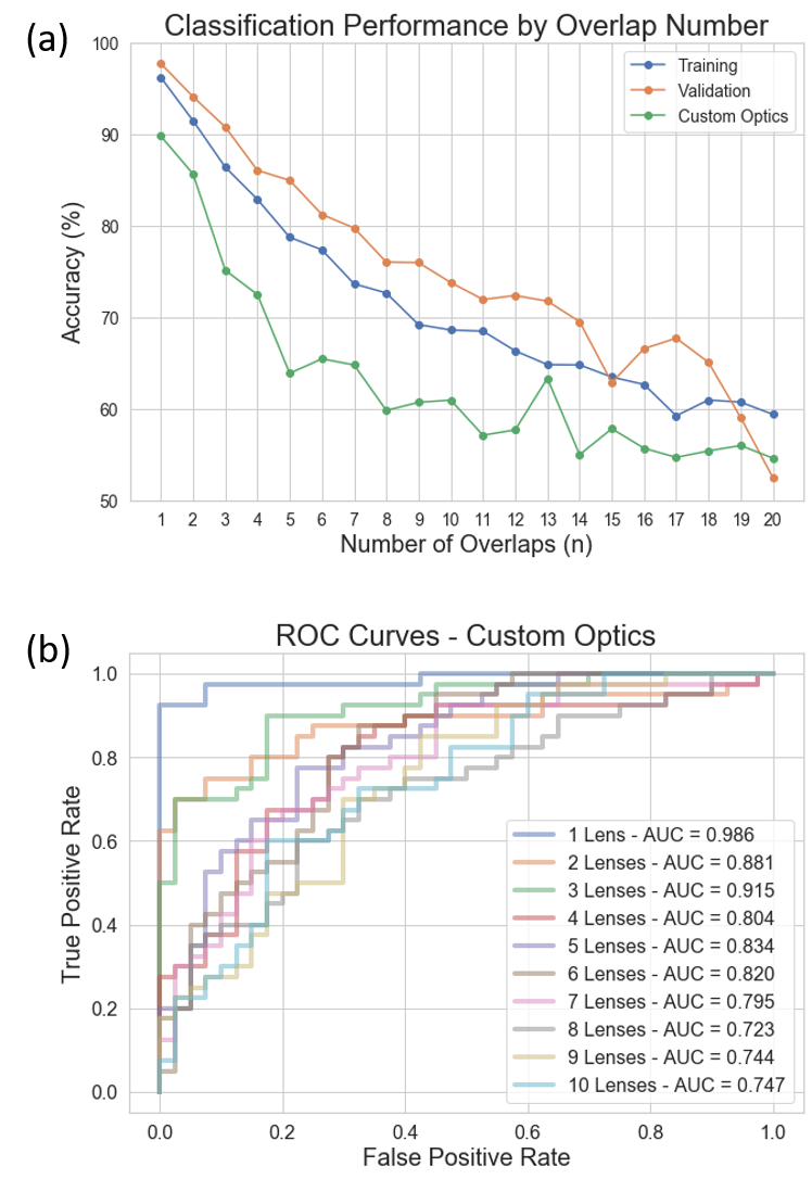
Figure 6. Classification accuracy and ROC curves under different overlapping numbers. The Custom Optics label indicates sampled gathered from the single lenselet configuration of the overlapped imaging setup. (a) Classification accuracy versus number of overlapped images n. (b) ROC curves and corresponding AUC values for the custom optics dataset for n = 1 to 10.
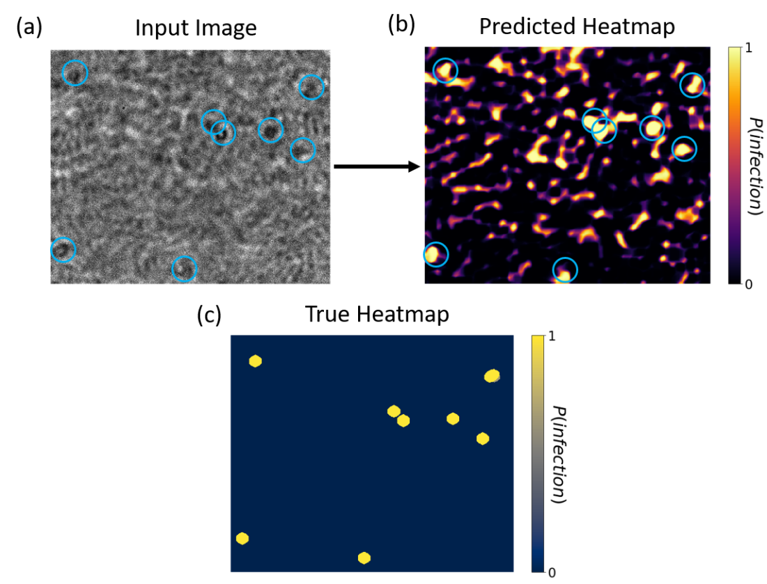
Figure 7. Classification of experimental P. falciparum image using our pre-trained overlapped DNN. (a) Experimental non-overlapped blood smear image with overlaid human annotations of parasite locations (blue circles). (b) Classification heat map correctly highlights most infection locations, despite being trained with imagery from a different microscope, but with a number of false-positive areas. (c) The true heatmap from human-annotated data is shown below.
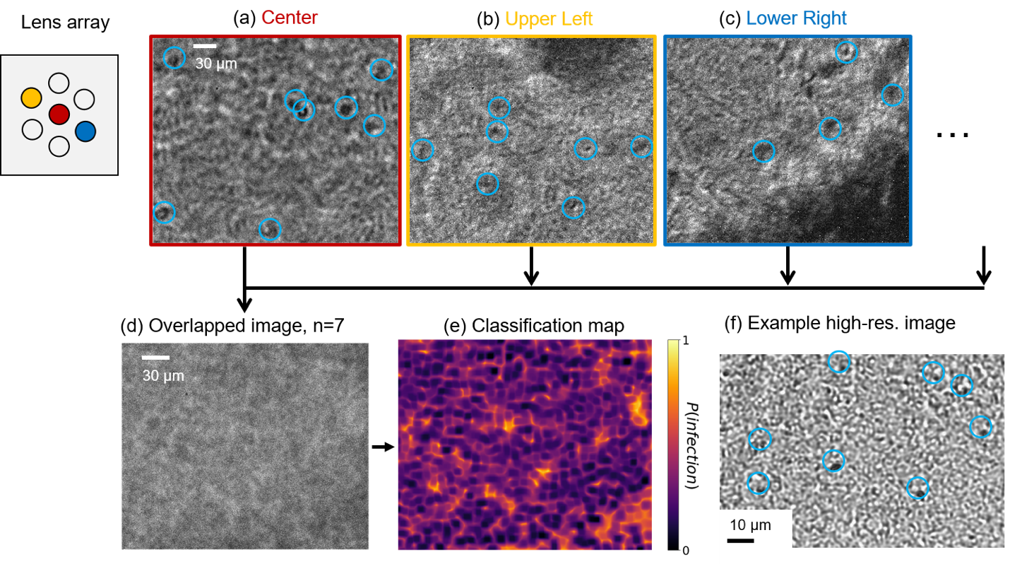
Figure 8. Classification of P. falciparum from within an n=7 overlapped blood smear image. Non-overlapped images from (a) center, (b) left-top and (c) right-bottom sub-lenses show suspected parasite locations marked with blue circles. (d) The n=7 overlapped image and (e) its classification heat map, created with our DNN pre-trained with digitally overlapped data. (f) Example high-resolution microscope image (NA=0.3) of similar thick blood smear slide with parasite locations marked.
Please click below for accessing Code and Data